Product Description
Product Parameters
Editing and broadcasting of main materials
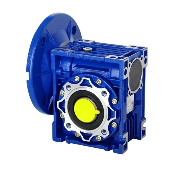
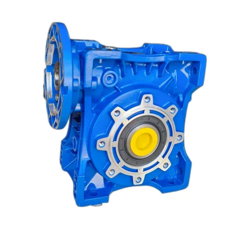
1. Body, die-casting aluminum alloy;
2. Worm shaft, 20 Crq steel, high temperature treatment;
3. Worm gear, nickel bronze alloy;
4. Aluminum alloy body, sandblasting and surface anti-corrosion treatment;
5. Cast iron body, painted with bIu RA5571.
Regular center distance specification editing and broadcasting
Center distance: 130 (unit: mm).
Output hole/shaft diameter: 11, 14, 18, 25, 28, 35, 42, 45 (unit: mm)
Detailed Photos
|
NMRV-063-30-VS–AS-80B5-0.75KW-B3 |
|||
|
NMRV |
Means hole-input with flange |
||
|
NRV |
Means shaft-input without flange |
||
|
063 |
Centre-to-centre spacing of worm-gear speed reducer |
||
|
30 |
ratio |
||
|
VS |
Double input shaft |
F1(FA) |
Flange putput shaft |
|
AS |
Single output shaft |
AB |
Double output shaft |
|
PAM |
|
80B5 |
Motor mounting facility |
|
0.75KW |
|
B3 |
Mounting position |
|
N2 |
NRV571 |
NRV030 |
NRV040 |
NRV050 |
NRV063 |
NRV075 |
NRV090 |
NRV110 |
NRV130 |
|
400 |
390 |
530 |
1571 |
1400 |
1830 |
2160 |
2390 |
3571 |
3950 |
|
250 |
460 |
620 |
1200 |
1650 |
2150 |
2520 |
2800 |
3530 |
4610 |
|
150 |
550 |
740 |
1420 |
1960 |
2450 |
2990 |
3310 |
4180 |
5470 |
|
100 |
630 |
850 |
1620 |
2250 |
2910 |
3430 |
3800 |
4790 |
6260 |
|
60 |
740 |
1000 |
1920 |
2660 |
3450 |
4060 |
4500 |
5680 |
7420 |
|
40 |
850 |
1150 |
2200 |
3050 |
3950 |
4650 |
5150 |
6500 |
8500 |
|
25 |
990 |
1350 |
2570 |
3570 |
4620 |
5440 |
6571 |
7600 |
9940 |
|
10 |
1350 |
1830 |
3490 |
4840 |
6270 |
7380 |
8180 |
10320 |
13500 |
|
|
|
|
|
|
|
|
|
|
|
|
A |
50 |
65 |
84 |
101 |
120 |
131 |
162 |
191 |
203 |
|
B |
38 |
50 |
64 |
76 |
95 |
101 |
122 |
151 |
163 |
Use and safety guarantee
1. Please check and confirm the matching intensity between worm gear reducer and mechanical equipment before use to assure that it is in the safety range of worm gear reducer performance parameters
2. Worm gear reducer has filled with WA460 lubricating oil. Please replace the lubricating oil after the first starting of 400 hours and after then 4000 hours for lubricating oil replacing cycle
3. There should be enough lubrication in worm gear box and keep regular check with the oil level.
4. When installation. please be careful to avoid sharp instruments bruising the oil seals on output shaft to cause leakage
5. Please confirm the rotation direction before mechanical connection. If the rotation direction is not correct, it will possible injury or damage the devices
6. Please set safety covers in rotating position to avoid of injuring
7. Please pay full attention: it is very dangerous if there is off or falling when movin
/* January 22, 2571 19:08:37 */!function(){function s(e,r){var a,o={};try{e&&e.split(“,”).forEach(function(e,t){e&&(a=e.match(/(.*?):(.*)$/))&&1
| Hardness: | Hardened Tooth Surface |
|---|---|
| Installation: | 90 Degree |
| Layout: | Expansion |
| Gear Shape: | Bevel Gear |
| Step: | Single-Step |
| Type: | Gear Reducer |
| Samples: |
US$ 30/Piece
1 Piece(Min.Order) | |
|---|
Advantages of Using Worm Gear in an NMRV Gearbox
Worm gears offer several advantages when used in an NMRV gearbox:
1. High Reduction Ratio: Worm gears provide a high reduction ratio in a compact form, allowing for significant speed reduction in a single stage.
2. High Efficiency: While worm gears typically have lower mechanical efficiency compared to some other gear types, the design of the NMRV gearbox optimizes efficiency by using a bronze worm gear and a self-locking mechanism that minimizes backdriving.
3. Compact Design: Worm gears have a compact and space-efficient design, making them suitable for applications with limited installation space.
4. Smooth and Quiet Operation: The meshing of worm gears and the helical design of the worm result in relatively smooth and quiet operation.
5. Self-Locking: Worm gears inherently have a self-locking characteristic, meaning that the gear cannot easily be back-driven by the worm. This property is beneficial for applications where holding position without external locking mechanisms is essential.
6. High Torque Capacity: Worm gears can transmit high torque loads, making them suitable for applications that require high torque output.
7. Simple Lubrication: The design of the NMRV gearbox allows for efficient lubrication of the worm gear, ensuring optimal performance and longevity.
These advantages make worm gears a popular choice for NMRV gearboxes in various industrial applications, where their characteristics contribute to reliable and efficient power transmission.
Lubrication for an NMRV Gearbox
Lubrication is essential for the proper functioning and longevity of an NMRV gearbox. The type and amount of lubricant required may vary depending on the gearbox model and manufacturer. Here are the general lubrication practices:
- Recommended Lubricants: Use the lubricants specified by the gearbox manufacturer. Typically, high-quality gear oils with the appropriate viscosity and additives are recommended.
- Initial Fill: Prior to the gearbox’s first operation, ensure that it is properly filled with the recommended lubricant to the correct level. Follow the manufacturer’s guidelines for the proper quantity.
- Lubricant Change: Regularly change the lubricant according to the manufacturer’s recommended intervals. Over time, lubricants can degrade due to heat and contamination, which can affect gearbox performance.
- Temperature Considerations: Gearboxes operating in extreme temperatures may require lubricants with specific temperature ranges to ensure proper viscosity and protection.
- Checking Levels: Periodically check the lubricant level in the gearbox to ensure it is within the specified range. This can prevent damage caused by insufficient lubrication.
- Oil Analysis: Some gearbox systems benefit from regular oil analysis to monitor lubricant condition and identify potential issues before they cause significant damage.
Proper lubrication practices contribute to reduced friction, wear, and heat generation within the NMRV gearbox, leading to improved efficiency and extended lifespan.
Installing an NMRV Gearbox
Installing an NMRV gearbox requires careful attention to ensure proper alignment and secure attachment. Here’s a general guide to the installation process:
- Prepare the Workspace: Ensure you have a clean and organized workspace with the necessary tools and equipment.
- Positioning: Place the NMRV gearbox in the desired position on your machinery, making sure it aligns with the input and output components.
- Alignment: Ensure that the input shaft of the gearbox is aligned with the driving shaft from the power source. Misalignment can lead to premature wear and reduced efficiency.
- Mounting: Securely mount the NMRV gearbox to the machinery frame using appropriate fasteners. Follow the manufacturer’s recommendations for torque specifications.
- Input Coupling: Connect the input shaft of the gearbox to the driving shaft using a suitable coupling. This coupling should be properly aligned to avoid unnecessary stress on the gearbox components.
- Output Coupling: Similarly, connect the output shaft of the gearbox to the driven component using an appropriate coupling.
- Lubrication: Before operation, make sure to fill the gearbox with the recommended lubricant to ensure proper gear meshing and reduce friction.
- Testing: Run the machinery briefly to check for any unusual noises, vibrations, or leaks. Make any necessary adjustments.
It’s crucial to follow the manufacturer’s installation guidelines and specifications to ensure a smooth and trouble-free installation process. Proper installation contributes to the longevity and reliable performance of your NMRV gearbox.


editor by CX 2024-04-10