The NMRV series is one of the most widely used types of speed reducers in the modern mechanical transmission industry. Renowned for its compact design, versatility, and cost-effectiveness, it plays a critical role in countless automated and manufacturing processes. Based on a comprehensive technical outline, this article provides an in-depth analysis of the NMRV reducer.
I. Basic Cognition of the NMRV Reducer
Product Definition & Industry Positioning
The NMRV reducer (often referred to as an aluminum alloy worm gear reducer) is a highly standardized power transmission device. Positioned as a versatile, mid-to-light duty reducer, it is the modern evolution of the traditional cast-iron worm gearbox, designed to meet the industrial demand for lightweight, modular, and aesthetically pleasing equipment.
Development History & Technical Evolution
Initially popularized by Italian manufacturers (like Motovario), the “RV” series revolutionized the market by replacing bulky cast-iron housings with die-cast aluminum alloys. Over the decades, it evolved from a simple power transmission unit into a highly precise, modular system capable of seamless integration with various standard electric motors (IEC/NEMA).
Core Advantages & General Applications
- Advantages: Compact size, excellent heat dissipation, rust resistance, high weight-to-output ratio, and flexible mounting options.
- General Scenarios: Ideal for applications requiring high speed-reduction ratios in limited spaces, such as conveyor systems, packaging machines, and automated assembly lines.
• RV Reducer: A general term for worm gear reducers, often referring to the older, broader category.
• NRV Reducer: Specifically refers to the reducer unit without an input flange for a motor (it features a solid input shaft instead).
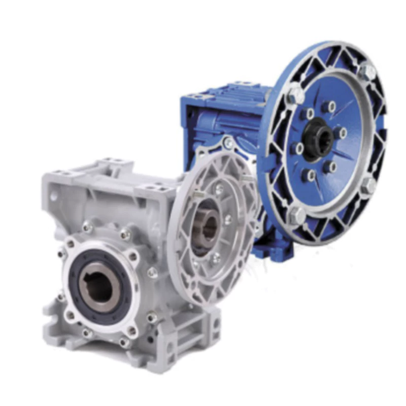
• NMRV Reducer: The “M” stands for “Motorized.” It comes equipped with an input motor flange, designed for direct and easy coupling with standard electric motors.
II. In-Depth Analysis of Core Working Principles
The Basic Logic of Worm Gear Meshing
The NMRV reducer operates on the principle of worm and worm wheel meshing. A threaded input shaft (the worm) drives a toothed wheel (the worm gear/wheel). Because the axes of the worm and the wheel are perpendicular (90 degrees) and non-intersecting, it allows for a highly compact right-angle drive setup.
The Process of Speed Reduction and Torque Multiplication
As the motor turns the worm, the worm’s screw-like threads push against the teeth of the worm wheel. For every full 360-degree rotation of a single-thread worm, the worm wheel advances by only one tooth. This results in a massive reduction in rotational speed, which is directly converted into a proportional increase in output torque.
Self-Locking Characteristics: Formation and Boundaries
Formation: A unique feature of worm gears is “static self-locking.” When the lead angle of the worm thread is extremely small (usually less than 5 degrees), the friction between the gears prevents the worm wheel from driving the worm backwards.
Boundaries: Self-locking is typically only reliable at high reduction ratios (usually 1:50 and above). It is not absolute; vibrations or dynamic loads can break the self-locking state, so it should not be solely relied upon as a safety brake.
Dynamic vs. Static Efficiency
- Static Efficiency: The efficiency when the reducer starts from a standstill. It is generally lower due to the initial friction needed to break the static oil film.
- Dynamic Efficiency: The running efficiency once the reducer is in motion. While higher than static efficiency, worm gears naturally lose some energy to sliding friction (heat), meaning they are less efficient than helical gears.
Low-Noise and Smooth Transmission
The continuous sliding action between the worm and the gear teeth, combined with a consistent bath of lubricating oil, ensures that the meshing is remarkably smooth. This continuous contact drastically reduces vibrations and operational noise.
III. Complete Structural Breakdown
The NMRV reducer is built around three primary systems: the external housing, the core transmission pair (gears), and the accessory components.
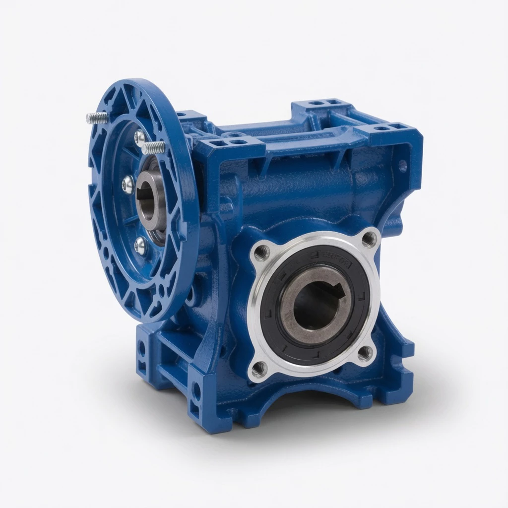
1. Housing Section
Material: Small to medium sizes (025–090) use high-quality aluminum alloy die-casting, which is lightweight and rust-proof. Larger sizes (110–150) use cast iron for higher structural rigidity to handle immense torque.
Design: Features a “square box” design with a smooth exterior for easy cleaning and high-surface-area cooling fins. It boasts a multi-face installation design, allowing it to be mounted from almost any side.
2. Core Transmission Pair
Worm Shaft: Made from high-quality alloy steel (such as 20CrMnTi). It undergoes carburizing and quenching heat treatments to achieve a highly hardened surface, followed by precision grinding to ensure accuracy and reduce friction.
Worm Wheel: Cast with wear-resistant tin-bronze or aluminum-bronze alloys. The softer bronze sacrifices itself slightly over time, protecting the harder steel worm shaft and ensuring a long, reliable operational life.
3. Accessory Components & Special Designs
Bearings & Seals: Tapered roller or deep groove ball bearings are used to handle both radial and axial loads. Premium lip seals prevent lubricant leakage and keep dust out.
Special Designs: Features like double oil sight glasses and multiple oil filler/drain plugs are designed so that operators can easily fill, drain, and check oil levels regardless of the unit’s mounting orientation.
IV. Full Series Parameters and Specifications
Size Specifications
The NMRV line typically covers 9 standard frame sizes: 025, 030, 040, 050, 063, 075, 090, 110, and 130 (and sometimes 150). The number denotes the center distance (in mm) between the worm and the worm wheel.
Power, Torque & Ratios
- Power capacity: Ranges from fractional horsepower (e.g., 0.06 kW for micro applications) up to robust industrial capacities (15 kW).
- Output torque: Ranges from a mere 2 Nm up to a massive 1,500+ Nm, depending on the frame size and ratio.
- 11 Standard Ratios: Usually available in single-stage ratios of 5, 7.5, 10, 15, 20, 25, 30, 40, 50, 60, 80, and 100.
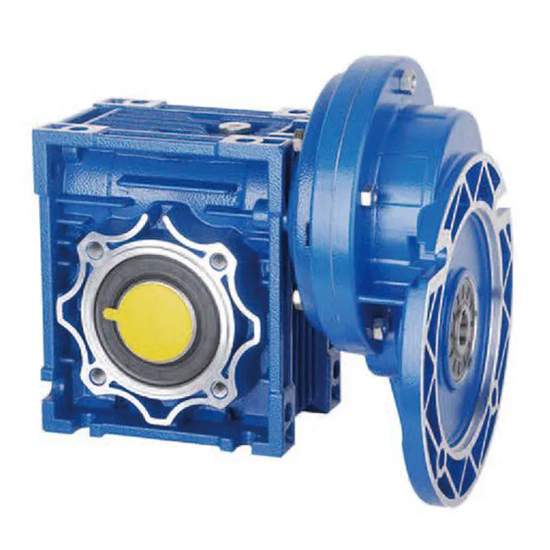
Input and Output Variations
Input: Standard motor flanges (B5, B14), solid input shafts, or servo motor adapters.
Output: Standard hollow output shafts, single solid shafts, double solid shafts, or output flanges for specific machine integration.
V. Mainstream Industry Applications
Light Manufacturing
In the food, textile, and printing industries, the NMRV’s aluminum body is highly favored because it does not flake paint or rust easily. It drives dough mixers, fabric rollers, and print cylinder adjustments smoothly and quietly.
Automation Field
For conveyor lines and small smart equipment, the compact square shape allows the reducer to be tucked away in tight chassis spaces, providing reliable power for material handling, robotic arms, and sorting belts.
Special Working Conditions
Low Temperature: With the correct synthetic oil, NMRV reducers can operate in cold-storage environments.
High-Frequency Start/Stop: The relatively low inertia of the internal components makes them highly responsive to the rapid starting, stopping, and reversing typical in packaging machinery.
VI. Installation and Maintenance Guide
Installation and Alignment
Multi-Position: The reducer can be mounted omnidirectionally (V5, V6, B3, B8, etc.).
Alignment: Absolute concentric alignment between the motor, reducer, and driven load is critical. Misalignment causes excessive radial stress, leading to premature bearing and oil seal failure.
Lubrication Standards
- Sizes 025 to 090 are usually pre-filled with high-quality synthetic oil for life and do not require ventilation plugs or regular oil changes under standard conditions.
- Sizes 110 and up use mineral oil. For these, the oil should be changed after the first 400 hours of break-in, and then every 4,000 working hours thereafter.
Daily Inspection and Troubleshooting
Inspections: Regularly check for abnormal noise, excessive surface temperature (up to 80°C/176°F is generally acceptable), and visible oil leaks around the seals.
Troubleshooting: If the unit runs abnormally hot, it may indicate overfilling of oil or severe mechanical overload. Oil leaks usually indicate a worn oil seal or a blocked breather valve (on larger units).
VII. Selection Pitfalls and Adaptation Advice
A common pitfall is selecting a reducer based only on the motor horsepower. A proper selection must account for the required output torque and the desired output RPM.
Factoring in the Service Condition (Service Factor)
The Service Factor (f.s.) is crucial. A reducer running 8 hours a day on a uniform load might need a service factor of 1.0. However, if the same reducer is subject to heavy shock loads and runs 24/7, the service factor must be increased (e.g., 1.5 to 2.0), requiring you to size up the reducer frame.
Accessories and Mounting Adaptations
Couplings: When connecting solid shafts, always use flexible couplings to compensate for minor misalignments and absorb shock.
Torque Arms: If shaft-mounting the reducer (hollow shaft sliding over the machine shaft), use a designated torque arm bracket to anchor the reducer body, rather than bolting the housing rigidly, to allow for slight flexing.